Frequently Asked Questions
Table of Contents
Table of Figures
Many Level 1 requirements describe what the architecture has to allow in the way of operations. However, any mission determines which of these are to be implemented in its specific radios to support the mission’s needs. In NASA-STD-4009A, requirements were written in a layered way so as to describe many architectural requirements in terms of applications, devices, services, other artifacts, and how they are used to perform the necessary functions.
The Level 1 requirements include responding to commands sent from an external source for remote reconfiguration, remote reprogrammability, processor sharing, and commanded Built-In-Test (BIT) and status reporting. These Level 1 requirements become part of the rationale for those requirements in NASA-STD-4009A pertaining to the startup and configuration of the radio as well as commanding the radio and obtaining information back about the configuration and command success.
4.2 Operating Environment (OE) Requirements
The STRS OE, as used in NASA-STD-4009A, is the software environment in which the STRS applications are executed. Because an STRS radio is really a computer, it has an operating system (OS) usually created separately from the STRS infrastructure. Using an OS promotes the STRS goals and objectives for flexibility, decreasing development time and cost, and increasing the reliability of SDRs, by leveraging existing standards, resources, and experience. A real-time operating system (RTOS) is likely to be used to meet timing deadlines and to support other operations, even though most of the real-time capability currently resides in field programmable gate arrays (FPGAs). Furthermore, an OS will need real-time capability if the general purpose processors (GPPs) are faster and assume more of the telecommunication functions or if the mission’s telemetry requirements are stringent enough to warrant using an RTOS to be able to achieve processing constraints.
The Portable Operating System Interface (POSIX) is a standard that is used by many OSs. Therefore, POSIX was chosen to implement certain functions missing from the list of STRS Application-provided methods to minimize duplication of methods between STRS and POSIX.
4.3 Documentation Requirements
NASA-STD-4009A requires specific information to be delivered with an STRS-compliant platform and application. This information is requested to support the goals and objectives for extensibility, adaptability, portability, reusability, and vendor independence. The specific mission procuring the platform and/or application will require additional documentation to integrate and operate the platform and/or application with the rest of the system for the mission.
The hardware abstraction layer (HAL) documentation is required by STRS to allow, for example, the independence of the providers of the infrastructure and the FPGA. The basic goals and objectives include accommodating advances in technology with minimal rework (extensibility) and maintaining vendor independence. The STRS infrastructure has access to the HAL, and the HAL is specific to a platform. Since STRS is designed for the applications to be as portable as possible, STRS hides the HAL from the STRS application using a bridge pattern so that an STRS application can use a standardized application program interface (API) to interact with any specialized hardware.
Because of size, weight, and power (SWaP) restrictions for space, many of the requirements in the Department of Defense’s Software Communications Architecture (SCA) version 2.2 were eliminated for STRS. These include eliminating the requirement for Common Object Request Broker Architecture (CORBA) and the onboard parsing of the Extensible Markup Language (XML). Although object-oriented Unified Modeling Language (UML) diagrams were used for parts of the description to clarify relationships, they did not become part of the requirements. As described in the Case Study, STRS was able to use almost the same PIM as the OMG’s SWRADIO to come up with a very different implementation.
Because the STRS architecture needed to support a C language interface to minimize SWaP, a pure object-oriented approach was unsatisfactory. To encapsulate functionality in a consistent manner, APIs were defined and the corresponding #include files were required to constrain the method signatures appropriately. A subset of the infrastructure APIs was required to call the appropriate application API. Because of the C language interface, the methods were differentiated so that the STRS infrastructure APIs had a different naming convention and two additional arguments:
- The fromWF argument in many of the STRS infrastructure APIs is the handle identification (ID) used to indicate who the caller or source is.
- The toWF argument in many of the STRS infrastructure APIs is the handle ID used to indicate who the responder or destination is. The STRS infrastructure uses the toWF to determine which application, device, file, or queue is to be used to perform any further processing. Then the infrastructure-provided method usually calls the corresponding Application-provided method.
A handle ID is used to control access to applications, devices, and so forth. The fromWF and toWF may be used by the infrastructure to validate whether the method is allowed to be called and to keep track of the history of the method call for error processing. They are used by the infrastructure when creating log messages to indicate the source of an error.
It is up to the infrastructure provider whether the handle ID is an index into a table, or an address of a structure, or a hash value used to look up the information that the infrastructure uses to access the application, device, file, or queue. The only restriction imposed by STRS is that a negative value indicates an error. It is the responsibility of the infrastructure to keep any additional information needed to intelligently populate the error logs. Each application is informed of its own handle ID and handle name using APP_Instance. The application uses its own handle ID as the fromWF argument to most STRS infrastructure-provided methods. There should be a handle ID for the infrastructure (or portions thereof) to indicate when the infrastructure is the source for error messages.
After considering the functionality required by the use cases and OMG SWRADIO profile, there needed to be APIs to standardize additional portions of the software. Therefore, APIs were created for devices, message queues, files, and timing. Some others were left to POSIX to implement.
4.5 Configuration File or Script File Recommendation
Configuration files or script files are recommended as a self-documenting way for the STRS infrastructure to start STRS applications into a known state to support the Level 1 requirements for remote partial configuration, reconfigurability, adaptability, automated system recovery and initialization, and multiple waveform support. The basic requirement derives from the need for each component to start in a known state. Requirement STRS-1 produces a known state for the platform. Using application configuration files or script files produces a known state for the applications. The infrastructure configuration files are suggested to allow for evolution of the hardware and software in a standard way.
Using an application configuration file addresses the variability regarding what resources may be needed by the application, what variables need to be defined, and what state changes need to be made. There is not necessarily a one-to-one correspondence between an application and a loadable file. A loadable file can contain parts of multiple applications; likewise, an application can span multiple loadable images. In a common case, a single application has both a GPP part and an FPGA part. Another case occurs for the OS-like Real-Time Executive for Multiprocessor Systems (RTEMS), a free open-source RTOS designed for embedded systems, which does not support dynamic loading. In that case, there is no need to include separate information on the GPP part of an application, since the build process does not make a loadable image for the application alone, separate from the infrastructure.
The application configuration files allow for the same application to be configured for different situations. For example, the environment may vary over the life of the radio and parameters may need to be adjusted accordingly. Another example might be allowing the original frequencies defined in a configuration file to be updated to avoid interference. It is less risky to send a short data file to the radio than to send a full software load. A current example for one of the SCaN Testbed SDRs is that the software and/or configurable hardware design has to remain stable at a certain point in the development process so that code review and test can be completed. However, there are parameters that are environmentally sensitive and can only be determined by testing under environmental conditions that simulate the conditions of space. These parameters are determined and entered into the application configuration file. A new application configuration file is then added to the SDR, but the software and configurable hardware design used for the code review and test remain unchanged.
When the waveform application is started, the state, resources, and the configurable parameters can be specified in a configuration file or script so that any reinitialization is predictable. For example, if the radio needs to cycle power to correct some glitch, it should be able to do so and restart the application without intervention. The project manager may require the inclusion of “initial or default values for all distinct operationally configurable parameters.” The “operationally configurable parameters” were those that could be configured using the STRS_Configure/APP_Configure commands instead of using subordinate parameters that do not have to be configured separately or using merely queryable parameters. For example, if a data item can be initialized in multiple ways such as having parameters for both frequency and wavelength, only one would need to be configured. Also, a parameter could be queryable but not configurable (e.g., temperature, location, and power consumption).
When the project manager specifies a requirement for a configuration file, XML is recommended as a good starting point. The reasons for using XML for the predeployed application configuration files are as follows:
- Using XML allows the data to have a standardized format that is easily created, read, and used by multiple entities.
- XML is easy to learn, does not require much overhead, and is a World Wide Web Consortium (W3C) free and open standard.
- Using XML saves time and money since tools already exist for displaying, editing, validating, parsing, and other functions.
- Using XML allows the data to be self-documenting.
- An exact format for the predeployed configuration files is not specified because the infrastructure for each vendor may need different information to start an application. The data in the application configuration files may not always be just name/value pairs.
- Using XML allows for hierarchical as well as sequential data. Using hierarchical data allows for greater complexity. Using XML does not hinder the data from being used sequentially or in a specific order.
- XML is easily transformed to more compact forms such that only the relevant subset appears in the deployed configuration file. The minimum data could be identification, any resources loaded, any parameters configured, and ending state information.
- Using XML allows the STRS integrators to be able to verify that the data they enter meet some specified criteria so that the creation of the deployed configuration file will work properly.
- STRS began as an approach to adapt SCA for NASA space applications. A waveform application was implemented using SCA and from that, it was apparent that having CORBA and an XML parser in the radio added quite a lot to the complexity, size, and weight. STRS eliminated the need for CORBA, dynamic features, and an XML parser in the OE. So, the best resolution was having XML to start with and a processed file to deploy on the radio.
- The SCA’s properties files in XML could be used for STRS with minimal changes. An Extensible Stylesheet Language Transformation (XSLT) could be written to transform an SCA properties file into any deployed format.
- Using XML allows validation of input values. Part of the compliance testing is to verify that the configuration file follows the format specified in the schema. Using an XML schema saves NASA from having to keep a different validation tool for each vendor.
- Using XML allows data to be labeled with tags and attribute names so that the data are more easily validated and changed. The minimum was specified for the format of the application configuration files so that each vendor could use the format appropriate to that vendor’s implementation. For example, here are some alternatives for a “wait” command in XML:
- <command>wait 100</command>
- <wait>100</wait>
- <wait delay=”100″/>
- <wait delay=”100″ units=”microseconds”/>
- <wait> <delay>100</delay> <units>microseconds</units> </wait>
Validation is difficult for alternative (1) using a schema. When the data “100” is separately identified, as in alternatives (2)-(5), it is easier to validate using a schema. When “100” is labeled as a delay, it is easier for multiple entities to identify and modify. Alternative (3) is not really better than (2) because the word delay does not add to the definition of the number significantly but adding the units does. When the “100” is labeled as a delay in microseconds, as in alternatives (4)-(5), it is even easier for multiple entities to identify and modify. Both (4) and (5) contain the same explanatory information and may be clearly checked by a schema. Which one may be considered optimal depends on the ability to transform the data into a deployed format.
XML 1.0 is recommended because the http://www.w3.org/ standards state that even though XML 1.1 is the current version, “You are encouraged to create or generate XML 1.0 documents if you do not need the new features in XML 1.1.” Furthermore, an error was obtained when using XMLSpy, a commercial-off-the-shelf (COTS) software product for testing with XML 1.1.
To avoid the drawback of requiring an XML parser to be part of the radio, the STRS allows the configuration files to be preprocessed into a simpler form. Although XSLT is suggested in NASA-STD-4009A as a simple mechanism for this transformation, it is not required. Alternatively, the preprocessing could be handled by a program or script. Although a manual process using a text editor is not impossible, an automated process is preferred.
The following state diagram, figure 1, STRS Application Recommended State Diagram, shows that an STRS application can have various states during execution. The files for the STRS application are to be accessible before execution can begin.
- STRS_InstantiateApp causes the deployed configuration file to be parsed and APP_Instance or the constructor to be called such that the STRS application starts in the INSTANTIATED state, but it may be transitioned to another state if specified in the STRS application configuration file.
- STRS_Initialize calls APP_Initialize on the appropriate STRS application.
- APP_Initialize transitions the STRS application to the STOPPED state upon successful completion.
- STRS_Start calls APP_Start on the appropriate STRS application.
- APP_Start transitions the STRS application from the STOPPED state to the RUNNING state upon successful completion.
- STRS_Stop calls APP_Stop on the appropriate STRS application.
- APP_Stop transitions the STRS application from the RUNNING state to the STOPPED state upon successful completion.
- When either APP_RunTest or APP_GroundTest is called, the application may be transitioned from the STOPPED state to a TESTING state, if necessary.
- STRS_ReleaseObject calls APP_ReleaseObject on the appropriate STRS application.
- The FAULT state may be set by the STRS application or detected by the fault monitoring and recovery functions, but any recovery is managed by the STRS infrastructure or by an external system.
The STRS application internal states shown in figure 1 are suggested. The STRS application developer may define and use any additional internal states that the STRS application developer sees fit. The infrastructure may use any additional states that are deemed necessary.

4.6 Roles and Responsibilities
For STRS, roles are specified as abstractions for the responsible organizations. The roles and corresponding organizations are expected to change at different stages of the radio’s life cycle. For example, a developer or provider of some component may act as an STRS integrator for that component and other components at a subsequent stage of production. Then, that STRS integrator may act as a provider for the next stage. NASA’s goals are to promote vendor independence, scalability, flexibility, and extensibility while specifying the smallest number of clearly defined roles possible.
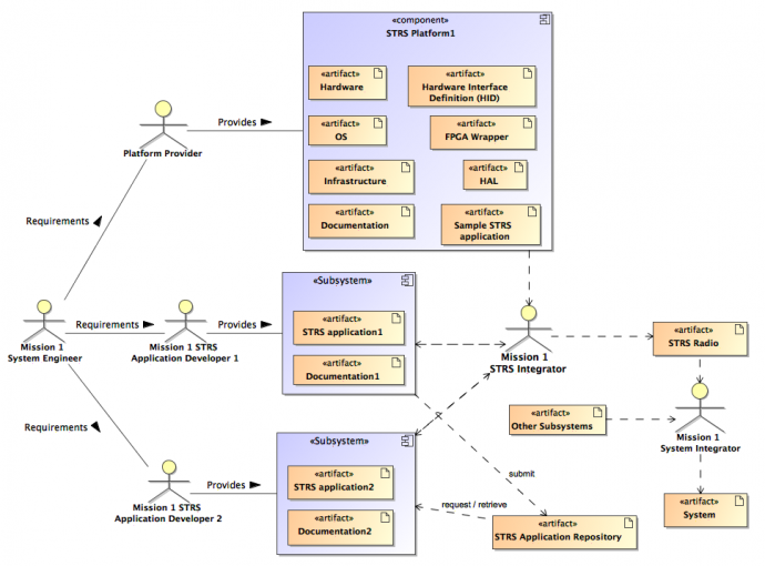
The basic roles that NASA-STD-4009A defines are the STRS platform provider, who delivers a platform upon which STRS applications can be executed, an STRS application developer who provides the desired functionality in the form of an STRS application, and an STRS integrator who is responsible for integrating the parts to work together. The STRS platform provider could subcontract for hardware and software, but the responsibility for coordination, integration, and delivery of the infrastructure and related artifacts would reside in one STRS platform provider organization.
The STRS platform provider would usually act as STRS application developer and STRS integrator for at least a sample application. The roles and associated products are depicted in figure 2, Roles and Products.
The roles could have been broken down differently, allowing for various combinations of providers and integrators that could be very complex. Some suggested roles were as follows:
- Application developer or provider.
- Application integrator (OE + applications).
- Configurable hardware design provider.
- HAL/board support package (BSP)/drivers provider.
- Hardware integrator.
- Hardware parts supplier.
- Infrastructure provider.
- Kernel integrator (OS + POSIX + HAL).
- OE integrator (OS + POSIX + HAL + infrastructure).
- OE provider (OS + POSIX + HAL + infrastructure).
- Operator.
- OS provider.
- Platform integrator.
- Platform provider.
- POSIX provider.
- Radio integrator (OE + applications).
- Radio operator (concerned with the mechanics of commanding the radio).
- Spacecraft operator (concerned with the functionality of the radio in the larger sense of including ground operations, experimenters, i.e., consumers of the data flowing through the radio).
- System integrator (the entity that puts the radio into a system).
Some of these roles are duplicates or overlap one another. There were multiple interpretations for some of the roles, causing confusion. Therefore, the roles were simplified. Although a few operator roles were suggested, the operator roles have no STRS requirements, so these roles were not included. The operator roles are required for specific missions or projects rather than for the STRS architecture. There are no STRS requirements for specific external commands and how the commands and data get to the STRS radio. There are no STRS requirements for a specific process for an operator to turn the radio on and off, send configuration commands, consume and source data, deal with configuration management of software uploads, and other functions. There are no STRS requirements for the radio link parameters and for the actions of the experimenters and consumers of the data flowing through the radio. These types of requirements are mission-specific and have to be included in the requirements for the particular mission or project, which are in addition to NASA-STD-4009A requirements.
Document preparer roles and reviewer roles are not included, because STRS has no requirements concerning the process by which the documents are generated. There will be mission or project requirements for additional roles (including stakeholders) not mentioned here, for which STRS has no requirements.
5.1 How to Associate an FPGA with an STRS Application
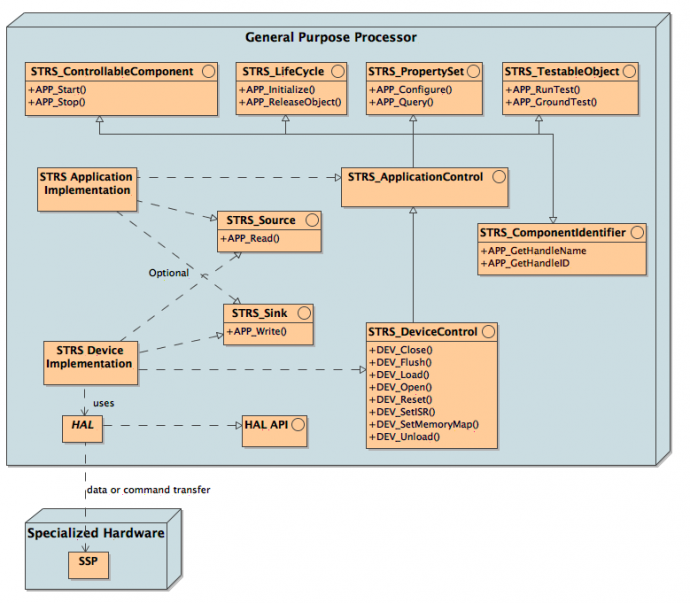
For an FPGA, there should be a corresponding STRS Device (GPP code) to control the FPGA and transfer data. The handle name of the STRS Device for each FPGA may be named differently, especially on different platforms. To make it easy for the STRS application to access the appropriate FPGA with maximum portability, the handle name of the STRS Device that corresponds to the appropriate FPGA should be a configurable attribute for the STRS application. The STRS application would use the attribute supplying the handle name to obtain the handle ID using STRS_HandleRequest. The application would use the resulting handle ID of the STRS Device to invoke the STRS Infrastructure-Provided Application Control API methods (NASA-STD-4009A, section 7.3.2) and STRS Infrastructure-Provided Device Control API methods (NASA-STD-4009A, section 7.3.6) to interact with the FPGA. A likely implementation would have any methods in the STRS Infrastructure-Provided Device Control API invoke the corresponding method in an STRS Device-Provided Device Control API. A sample of an STRS Device-provided Device Control API is shown in figure 5, STRS Application/Device Structure, as the Device API.
For example, there might be FPGA1 and FPGA2 available. If WF1 uses FPGA2, a configuration file for WF1 could contain a name/value pair to associate the name useFPGA with FPGA2. Let the function getValue obtain the value corresponding to the given name. Then, the STRS application could access the correct FPGA, as follows:
  STRS_HandleID fromID = APP_GetHandleID();
  char* fpgaName = getValue("useFPGA");
  STRS_HandleID fpgaID = STRS_HandleRequest(fromID, fpgaName);
  STRS_Result rtn = STRS_ValidateHandleID(fpgaID);
  if ( ! STRS_IsOK( rtn )) {
     STRS_Message msg = "Handle ID error for useFPGA.";
     STRS_HandleID errQ = STRS_GetErrorQueue(rtn);
     STRS_Log (fromID, errQ, msg, (STRS_Buffer_Size) sizeof(msg));
  }
An FPGA may be loaded directly by the infrastructure when it parses the configuration file, if supported, or may be loaded by an STRS_DeviceLoad call from the application GPP code. If the latter method is used, the name of the bitstream file should also be a configurable attribute set with the APP_Configure method. The STRS_HandleRequest method should be called to obtain the handle ID for the FPGA Device, and then the STRS_DeviceLoad method should be called for the FPGA to load the bitstream file. These STRS infrastructure calls may be performed in the APP_Configure directly or in the APP_Start method, as appropriate.
An FPGA may be configured directly by the infrastructure when it parses the configuration file or by an STRS_Configure call to the STRS Device for the FPGA call from the application GPP code. If the latter method is used, the handle name of the FPGA Device should also be a configurable attribute set with the APP_Configure method. The STRS_HandleRequest method should be called to obtain the handle ID for the FPGA Device, and then the STRS_Configure method should be called for the FPGA Device to configure the FPGA. These STRS infrastructure calls may be performed in the APP_Configure directly or in the APP_Start method, as appropriate.
Not all specialized hardware can be interrogated for its configuration; however, the infrastructure or the application may maintain any configuration data needed. The application has to implement APP_Query and, if appropriate, it should call the STRS_HandleRequest to obtain the handle ID for the FPGA followed by an STRS_Query call to the STRS FPGA Device to obtain the configuration data from the FPGA.
To push packets from an application, to a device, queue, file, or another application, STRS_Write is used. For generating packets in the same application used to send the packets,
APP_Write may be used directly. If an application acts as a sink of packets pushed, it has to implement APP_Write, #include “STRS_Sink.h”; and if C++, the class has to implement STRS_Sink.
To pull packets from a device, queue, file, or another application, STRS_Read is used. To pull packets from another module in the same application, APP_Read may be used directly. If an application acts as a source of packets pulled, it has to implement APP_Read, #include “STRS_Source.h”, and, if C++, the class has to implement STRS_Source.
When a call to an STRS method is made, a variable of type STRS_Result is usually returned. To ensure consistent testing for errors, where an error is usually a negative value, STRS_IsOK tests that variable of type STRS_Result for errors, and returns a true or false boolean variable. The value returned from STRS_IsOK is true when there is no error and false when there is an error so that appropriate action may be taken.
When an error is detected in the operation of the application, STRS_Log should be invoked using an error queue handle ID (STRS_FATAL_QUEUE, STRS_ERROR_QUEUE, or STRS_WARNING_QUEUE), and a descriptive message. The error queue handle ID can be determined using STRS_GetErrorQueue with the error return value as an argument. The error queues are monitored and passed to the infrastructure for further action.
The STRS methods use the error returns rather than using variable errno to indicate an error. STRS policy on errno is that it is undefined outside of the application methods. You cannot rely on it to indicate the particular error because it is not reset before system calls and may be reset to a different error later, before it is tested. It reduces portability by allowing different values on different operating systems with different compilers.
5.8 How to Make Multiple Instances of an Application
To create multiple instances of an application, be sure that the application is reentrant and that all pertinent data are configurable. Two configuration or script files may have to be created, if any of the initial data is different. A different handle name is specified for each instance. When using C language applications, there may be method name duplication, which is discussed further in section 6.10, C Language Naming Duplication.
5.9 How to Map Memory Locations
STRS Devices are allowed to use memory mapped locations in which storing/retrieving an item in shared memory automatically pushes/pulls the item to/from the specialized hardware. STRS Devices do not have to be portable, so non-standard methods may be encapsulated within an STRS Device. The STRS applications should not use the shared memory locations directly to communicate with the specialized hardware because that is not portable and violates the spirit of STRS. The addresses for the specialized hardware should not be defined in the application or its configuration file. Hard-coding of memory locations in an STRS application or STRS Device is strongly discouraged because hard-coding would limit the independence of the software and configurable hardware design and may cause problems with verification and validation if any FPGA code is changed that would affect that location.
There is no requirement that an STRS Device use configuration or script files containing location information, but it is strongly encouraged to be configured rather than hard-coded. Configuration data are usually specified in a configuration file where the OE parses the configuration file to call STRS_Configure and that calls APP_Configure in the STRS Device to accept the configuration data. However, there is nothing in the standard that restricts the OE from calling other method(s) such as DEV_SetMemoryMap(map) to specify more complicated configuration data. Similarly, a script file may be executed to call STRS_Configure and related commands.
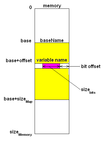
The shared memory locations should be specified in the configuration or script files for the appropriate STRS Device. In the example of a configuration file shown in Appendix A for MEMORYMAP and MAPVALUE, there is a base name, associated relative location, offset, size, and access. These are illustrated in figure 3, Memory Map. The location for an individual item is specified relative to the base name in addressable storage units. The location may also have a bit offset and bit length. Then, when the configurable item is modified, the mapped location is used. In the example of an STRS Device shown in figure 5, the OE can use the DEV_SetMemoryMap(map) method to configure the mapping in the STRS Device.
5.10 When to Use STRS_Log and STRS_Write
The two STRS infrastructure methods, STRS_Log and STRS_Write, have similar functionality except that STRS_Log adds a time stamp and possibly other identifying information. These methods should never be mixed for a given target. An STRS application developer should only write to the error queues using STRS_Log because the errors need to be identified further (STRS-54, STRS-55, STRS-56) and never with STRS_Write. Similarly, an STRS application developer should only write to the telemetry queues using STRS_Log because the telemetry data need to be identified further (STRS-57) and never using STRS_Write. Furthermore, the error queues are monitored for faults. An STRS application developer should only use STRS_Write to write buffered data to another application, service, device, file, or queue that does not require additional information added.
5.11 Difference Between Run Test and Ground Test
A run test is invoked using STRS_RunTest and implemented by APP_RunTest. A ground test is invoked using STRS_GroundTest and implemented by APP_GroundTest. A run test is invoked before or after deployment to determine whether the component is performing correctly. A ground test is generally invoked before deployment to perform unit testing and calibration. The ground tests help to automate and evaluate those tests. The term ground test was originally used to indicate testing for a satellite system, which is performed on the ground before launch.
Ground test may be invalid after deployment and indicates that such tests are normally completed before deployment and are not repeated thereafter. If allowed by the project and the ground tests will not be repeated after deployment, then the ground test code may be removed prior to deployment. The run tests and ground tests were separated because NASA generally requires significant testing prior to deployment; for example, vibration testing, environmental testing, radiation testing, etc.
5.12 When to Use Start/Stop, Load/Unload, and Open/Close
The commands STRS_Start, STRS_DeviceLoad, STRS_DeviceOpen are specified in NASA-STD-4009A along with the reverse commands, STRS_Stop, STRS_DeviceUnload, and STRS_DeviceClose. The following describes the interaction of these commands under various common circumstances.
Initialize (STRS_Initialize) is used while the application is in the STOPPED mode to set the application to a known initial condition. The application may be configured before and/or after initialize. Start (STRS_Start) is used to begin normal processing and change the state to RUNNING. If any part of the application is in specialized hardware, that portion needs to be loaded before starting. To load (STRS_Load) an STRS Device, the Device has to be opened (STRS_Open) first. It is suggested that any part executing in specialized hardware not begin execution upon being loaded but rather during the start process. Similarly, it is suggested that stopping execution (STRS_Stop) does not require any specialized hardware to be unloaded. Therefore, greater control is given to the application software for processing commands to start and stop waveform application operation in order to take advantage of windows of opportunity for execution as well as to promote consistency in control of the radio. Only certain allowed items may be configured after starting.
It is suggested that the STRS OE use configuration file(s) to start-up an application to a known initial state. STRS encourages that changeable data be specified in configuration files, rather than coding the data as constants within the application or device, so that greater portability and ease of modification is achieved. The STRS OE may process a configuration file to instantiate, open and load the device, initialize, configure, and start the application, or use any subset of these as determined by the project/mission and STRS platform provider.
As an example, the following use case is written for a waveform application using specialized hardware to send signals over the air to another radio assuming that the specialized hardware device has already been instantiated and initialized by the OE:
- Radio receives a command that a new waveform application is needed. This may be multiple commands received or one command that invokes a series of operations. In either case, those operations follow.
- OE checks for availability of the application and memory to instantiate it.
- OE instantiates application (STRS_InstantiateApp).
- OE initializes application (STRS_Initialize).
- OE opens specialized hardware device (STRS_DeviceOpen).
- OE loads specialized hardware device (STRS_DeviceLoad).
- OE configures application (STRS_Configure).
- OE starts application (STRS_Start).
The use case for the reverse process is as follows:
- The radio receives a signal to stop and remove the application. This may be multiple commands received or one command that invokes a series of operations. In either case, those operations follow.
- OE stops the application (STRS_Stop).
- OE unloads the specialized hardware device (STRS_DeviceUnload).
- OE closes the specialized hardware device (STRS_DeviceClose).
- OE releases resources for application (STRS_ReleaseResources).
If there is no specialized hardware device, the steps pertaining to such a device may be eliminated. If the application merely performs calculation, start may mean perform the calculation and, before each calculation, the data is reconfigured. Alternately, start may mean ready to perform the calculation and start invokes a thread that loops waiting for new data so that each time new data is obtained, the computation is performed. Similarly, for a waveform application, start may mean to tell the specialized hardware device to begin processing signals or alternately, start may invoke a thread to perform the communication functions. A separate thread is used so that other commands may be processed independently.
5.13 How to Read and Write Data
An application may read data using STRS_Read and write data using STRS_Write. A description of content, format, and usage of buffers is provided as part of the user documentation. As Consultative Committee for Space Data Systems (CCSDS) Electronic Data Sheets mature, these should be considered as precise machine-readable descriptions to facilitate reading and writing data. Currently, CCSDS Electronic Data Sheets are Red Book specifications 876.0 and 876.1.
It is suggested that CCSDS be used to document the format of buffers. CCSDS book 876.0 specifies “Electronic Data Sheets” (EDS), which is an XML schema for describing data exchange between system components. It provides a means to specify the exact format of the data, binary or otherwise, the types of interfaces provided by a component, as well as any handshaking or protocol-level requirements of an interface. The objective is to specify these details in a machine-readable language, and with sufficient detail such that it eliminates the need for a separate interface control document (ICD). The system components described can be physical hardware devices, where the device manufacturer would author the EDS, or software components where EDS can serve as a common interface description between the sender and receiver.
The STRS architecture does not dictate a specific data format for all APIs, leaving this decision up to application/waveform developers. By standardizing the description of the data format using EDS, flexibility is retained while still providing a compatibility point. Because the electronic data sheets are implemented in a machine-readable format, parts of the data exchange between components can be machine assisted, thereby easing the efforts required to port applications between different systems. Using the EDS, any other independently developed system or component that also implements the CCSDS electronic data sheet technology can exchange data with the component.
The core Flight System (cFS) is a platform independent reusable software framework and set of reusable software applications that is reused on NASA flight projects and/or embedded software systems at a significant cost savings. The cFS contains an implementation of the CCSDS electronic data sheets. The cFS-based STRS OE utilizes this technology to describe the sink and source interfaces as well as the various configurable properties of STRS applications, which aids portability to other cFS installations or other independently developed systems implementing EDS.
5.14 How to Add Asynchronous Publisher/Subscriber Functionality
A queue can be used to disassociate a publisher directly from a subscriber. The Pub/Sub implementation is synchronous. To get the asynchronous publisher/subscriber effect, the publisher writes to a queue and, in a different thread, a copy service reads from the queue and writes the data to a Pub/Sub to which the subscriber has registered. The copy service is to be configured knowing a queue source, a Pub/Sub sink, and the maximum number of bytes. Functionally, the copy service merely obtains the source and sink handle IDs and uses them to read from the source and write to the sink.
A copy service may be useful to copy other sources to other sinks. It may need additional options to do so, especially concerning initialization, finalization, and timing considerations. These will have to be handled on a case-by-case basis.
6.1 Fault State and Use of the ERROR, WARNING, and FATAL Queues
NASA-STD-4009A does not specify how the fault state is set or detected. The fault state may be determined in a number of ways as specified by the mission or project. When STRS_Log sends a message to the error queue or fatal queue, it is assumed that there is an error or fatal error in that component and that the fault state is set accordingly. The fault state could also be set when a Health Manager or Watchdog Timer detects a problem (neither of which is required). The fault state could also be detected when the telemetry returns improper values. The fault state as shown in the state diagram (figure 1) implies that the radio detects and possibly recovers; however, it could be designed so that the fault state is kept by the flight computer or equivalent.
The use of the ERROR, WARNING, and FATAL queues are expected to be defined more closely by the mission or project. The three relevant types of queues are as follows:
- The STRS_FATAL_QUEUE is the queue used when an STRS_FATAL error is encountered. STRS_FATAL_QUEUE denotes the queue for a unrecoverable error in an attempt to capture information about the situation in a logging trail used to reconstruct the original cause of the error. Furthermore, sending a message to the STRS_FATAL_QUEUE is one way of initiating an orderly shutdown and reboot of the radio to a known state. The processing for a fatal error could imply turning off the heartbeat; that is, rebooting the radio and, if that does not work, reloading the software and/or configurable hardware design. It could imply that additional diagnostic tests need to be run. It is up to the mission to define whether there are alternative ways of rebooting under different circumstances such as after trying three times. It may make a difference if the problem is overheating or if a bit has been changed in the radio so that it does not work properly.
- STRS_ERROR_QUEUE denotes the queue for a recoverable error. The most likely reason is an invalid set of configuration parameters. The recovery would be to get a valid set of configuration parameters.
- STRS_WARNING_QUEUE denotes the queue for a recoverable error that has little or no effect on the operation of the radio. The most likely reasons are trying to run a test in a state for which the test is not allowed, trying to configure or query a parameter when the value is not available in that state, or trying to run APP_Start when the application is already started.
6.2 Pub/Sub Messaging and Queues Need Clarification
In NASA-STD-4009A, a Pub/Sub is distinguished from a message queue. In a Pub/Sub, messages written to the message passing facility by one application are delivered to all subscribers of that publisher. The STRS does not require implementing Pub/Sub using the observer/publish-subscribe design pattern where the class inherits a notify method. The STRS is designed to work in C without inheritance, but the idea is that the publisher does not know the identity of the subscriber such that one or more applications or devices can funnel data to one or more different applications, devices, files, or queues. Figure 4, Sample Publisher-Subscriber Sequence Diagram, is just one possibility for a sequence diagram showing the creation and possible use of a messaging queue using one form of the publisher-subscriber paradigm.
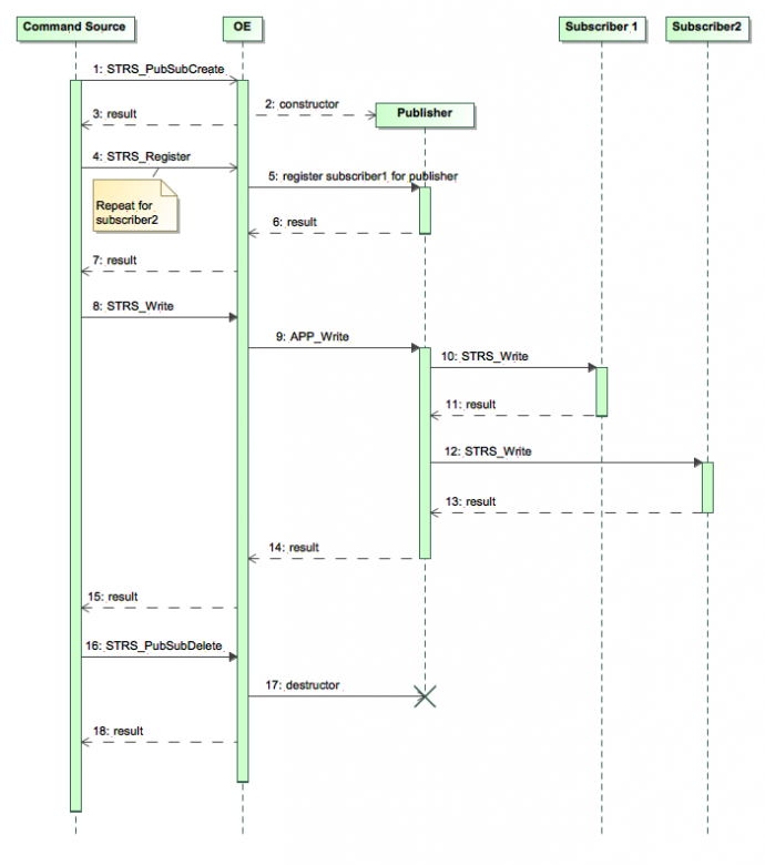
Detecting circularity and duplication is difficult with just the sequence diagram shown without adding additional methods. Circularity is where the message published eventually ends up back at the original publisher and is sent again in an infinite loop. Duplication is where the message published ends up at the same destination twice.
There is a problem of notification when it is a message queue. STRS_Write will put the message on the queue, but there is no standard way of determining when there is something waiting on the queue; that is, when does STRS_Read obtain it from the queue and when does the message get deleted from the queue? Also, can the queue fill up so that further messages are rejected? The resolution to the message-queuing behavior is not included in the current version of NASA-STD-4009A but has to be covered by the specific design for the mission or project.
An STRS Device is software that responds to both STRS Infrastructure-provided Application Control methods and STRS Infrastructure Device Control methods. An STRS Device is used to separate an abstraction in the form of its interface from its underlying implementation. An STRS Device is a bridge between a waveform application and the specialized hardware, used to insulate the waveform application developer from knowing how the data gets to its final destination. This encourages encapsulation of non-portable functionality. STRS Devices do not have to be portable. However, it will be advantageous to follow the STRS Device-Provided Device Control API wherever possible to maximize consistency and portability. The functionality of the STRS Device will need to be ported to each successive radio while allowing an application to access the STRS Device methods in a consistent way that makes the STRS applications more portable and more understandable.
If a waveform application intends to transfer a data value from/to the specialized hardware, the waveform application would contain the data value and the corresponding STRS Device would be used to transfer the data value from/to the specific location in the specialized hardware. The STRS Device could use memory mapping or POSIX or HAL, whichever is the documented way to get/set data in the specialized hardware while keeping the waveform application portable.
An STRS application is expected to use an STRS Device method to transfer data to and from the physical device. It was expected that the STRS Device configure/query methods could be used to get or set values, but there was a complaint that there were problems with performance, porting from legacy applications, and scheduling. Any exceptions to the standard are handled individually.
- An STRS Device can act as a sink by implementing APP_Write in the STRS Device. An STRS_Write/APP_Write is used to send data to a buffer in the specialized hardware. As an alternative, the STRS Device’s APP_Configure could be used.
- An STRS Device can act as a source by implementing APP_Read in the STRS Device. An STRS_Read/APP_Read is used to retrieve data from a buffer in the specialized hardware. As an alternative, the STRS Device’s APP_Query could be used.
- An STRS_Configure/APP_Configure is used to send the value of a name/value pair to the corresponding location in the specialized hardware.
- An STRS_Query/APP_Query is used to retrieve the value of a name/value pair from the corresponding location in the specialized hardware.
When an FPGA is implemented as an STRS Device, the FPGA may be loaded, configured, started, stopped, unloaded, and so forth, using the corresponding STRS Infrastructure Device Control API. There is no requirement that an STRS Device actually exists as separate software or hardware item. There is no requirement that the Device API is implemented as shown in figure 5. They are required when portability and reusability are desired as measured by their inclusion into the STRS Application Repository.
Many SDRs use memory mapped locations in which storing/retrieving an item in memory automatically pushes/pulls the item to/from the specialized hardware (see section 5.9). Other SDRs use special APIs that comprise the HAL to send/retrieve the item to/from a specific address in the specialized hardware. Still others use POSIX. Having the STRS Device as a portable interface for data transfer allows the HAL methods, POSIX methods, or memory mapping to be used as appropriate and easily changed. The STRS application can use the appropriate STRS Device methods when the STRS application just knows the handle name of the STRS Device, which gives more flexibility in configuring a data source or sink. For example, an application might be used to transmit data over the air obtained from a data source that might be configured as an application, device, queue, or file. Similarly, an application might be used to receive data over the air and send it to a data sink that might be configured as an application, device, queue, or file. Thus, an STRS Device may be used either to distribute functionality over multiple waveform applications or to abstract hardware functionality, further giving greater flexibility. This is analogous to redirection or pipes in UNIX .
Since STRS Devices are only partially standardized by the STRS Device-provided Device Control API, extra methods may be implemented in an STRS Device to be used by the OE to establish the proper use of the HAL. A DEV_SetMemoryMap method is suggested in figure 5 to specify how a named value is associated with the appropriate location in the specialized hardware. This may be a non-portable construction but it does not violate the NASA Technical Standard. The idea is to have the STRS application code as portable as possible with the STRS Devices as lean as possible.
6.4 How to Configure and Control SDR Hardware
The configuration and control of the SDR hardware depends on where the intelligence exists; that is, which software component knows how to configure and control SDR hardware? A combination of software components (waveform application, STRS infrastructure, STRS Device, and HAL) knows how to configure and control SDR hardware.
- The application knows about data values, the STRS Device knows about mappings in the GPP, and the HAL knows about how to take values and transfer them to the hardware.
- The STRS application should be the target component for the parameters it controls and could pass to an STRS Device those parameters that need to be passed to the HAL.
- STRS Application.
- The STRS application would control what data are configured.
- The STRS application has limited intelligence on how and where to enable the application to be portable.
- The STRS application knows the handle ID of the STRS Device to use.
- For example, an STRS application processes FREQUENCY, converts from floating point to integer in a format that is recognized by the STRS Device, and calls the appropriate method to configure the STRS Device.
- STRS Device.
- The STRS Device controls how data get to the FPGA or other hardware.
- The STRS Device knows how to send data to the proper register in the FPGA using the HAL.
- The HAL may be external functions or inline functions that know the mappings from data addresses to registers in the FPGA.
- STRS Infrastructure.
- The STRS infrastructure reads the configuration files or receives an external command and calls the STRS_Configure method for the appropriate target component.
- The STRS_Configure in the infrastructure calls the corresponding APP_Configure within the target component.
6.5 STRS Infrastructure Methods Do Not Belong to Any Class
The STRS infrastructure-provided methods beginning with “STRS_” do not belong to any class, since they have to be the same when called from C language implementations. If one is coding in C++, these methods should be defined using extern “C” {…}.
In NASA-STD-4009A, the STRS infrastructure provides the STRS infrastructure-provided Application Control API that supports application operation using the STRS
Application-provided Application Control API in section 7.3.1. The STRS Infrastructure-provided Application Control API methods (section 7.3.2) that begin with “STRS_” correspond to the STRS Application-provided Application Control API methods (section 7.3.1) that begin with “APP_” and are used to access those methods. The STRS infrastructure implements these methods for use by any STRS application or by any part of the infrastructure that is desired to be implemented in a portable way.
Since the C language is optional for STRS applications (see STRS-16, 18, 19), the STRS Application-provided application control methods beginning with “APP_” may belong to a class.
The clocks/timers are used for determining when something happens, how long something takes, and coordinating internal and external events, including timestamps for messages. As computer speeds increase, more real-time functions for communication may be performed in the GPP. Some functions currently in the FPGA(s) may be transitioned to the GPP when the GPPs are fast enough and capable enough to handle the additional signal processing functionality. These GPP functions would need access to high speed clocks/timers.
NASA-STD-4009A is designed to allow a clock/timer to be an extension of an STRS Device so that the functionality can be embedded in specialized hardware, if necessary. Multiple timers are only defined when they are required by the mission. An offset is usually specified to ensure that the clock is monotonically increasing from a previous power reset or is synchronized with another clock/timer.
Normally, each clock/timer has a base time, usually measured from when it is turned on. An offset may be used to keep the time monotonically increasing with each power cycle. An offset may also be used to coordinate with external events. The timing of external events, such as another satellite coming over the horizon or the availability of experimenters, may be used to power parts of the radio off and on so that the radio optimizes its power consumption and availability.
It is recommended that one clock/timer match the required timestamp for STRS_Log so that an application, service, the OE, or even STRS_Log itself could obtain that time in a consistent way. It was suggested that the time for the timestamp be retrieved via STRS_GetTime using the handle ID corresponding to handle name “STRS_DEFAULT_CLOCK_NAME” and kind given by property “STRS_DEFAULT_CLOCK_KIND”. The use of this handle ID for STRS_SetTime may be restricted as necessary.
As specified by the mission, there should be at least one clock/timer with an epoch fixed to some Earth time zone, e.g., Coordinated Universal Time (UTC), so that the epoch could be adjusted to seconds from 1/1/1970 0:0:0, known adjustments for leap days and leap seconds applied, and the standard POSIX time functions used. For example:
- From seconds to calendar time: Obtain the number of seconds from the TimeWarp object, apply any offset needed, and use gmtime_r to convert a given time since epoch (a time_t value) into calendar time, expressed in UTC in the struct tm format.
- From calendar time to seconds: Fill a struct tm with calendar time, convert to UNIX time using mktime, apply any offset, and create a TimeWarp object.
6.7 FPGA Partial Reconfiguration
Partial reconfiguration is the process of configuring selected areas of an FPGA after its initial configuration. Xilinx indicates that a bitstream file can contain all the configuration commands and data necessary for partial reconfiguration. Therefore, STRS_DeviceLoad will work, and no new methods need to be defined. Whether the partial reconfiguration is fully transparent to the application(s) running on the FPGA or requires stopping and restarting or reconfiguring any other application(s) depends on the specifics of the partial reconfiguration.
STRS compliance of a vendor- or partner-provided SDR is assessed by source code inspection, document inspection, configuration file inspection, adding an application containing a reference to each STRS infrastructure method and testing that application. The name of that application is the STRS Command and Compliance, also known as WFCCN. WFCCN may be compiled with an STRS infrastructure to determine whether or not there are any missing constants, typedefs, or structs. These techniques are described in the STRS Compliance Testing document, which should be reviewed because of their complexity.
Since many of the STRS requirements are source code requirements, a standard test suite cannot test them fully. Since STRS is designed to allow multiple vendors to work together, certain source code artifacts have to be made available so that a subsequent STRS application developer or STRS integrator can use the methods, constants, typedefs, and structs required. The following is an example of a problem that WFCCN cannot be used to find: One vendor used noncompliant
method signatures with int instead of STRS_Buffer_Size, but on that platform, both integer items compiled as the same type. Using a type that happens to correspond to the vendor’s implementation of an STRS type is not necessarily portable to the next platform.
The STRS compliance could be evaluated at and by each vendor or partner and the results shared and discussed in one or more workshops at various points in the project life cycle. This alternative is to be decided by the mission or project. A full release and delivery of all STRS OE source code is not required in order to perform STRS compliance testing. Each vendor or partner should inspect his or her own software and documents before delivery. However, NASA found its own review to be invaluable to ensure greater compliance and promote understanding of differences among submitters.
Once the STRS radio artifacts are tested for STRS compliance, any noncompliances will be reported to the supplier and the mission or project, along with any suggestions. It is the responsibility of the mission or project to decide whether to grant deviations and waivers for any noncompliances that are not resolved.
6.9 Configuration Files Examples
To help the reader and implementer of the STRS architecture understand the development and use of the configuration files described in Appendix A, Example Configuration Files, an example of a configuration file based on that format was developed. This example of a configuration file, for a sample application WF1, is shown in this NASA Technical Handbook in figure 6, Example of Predeployed Configuration File for Appendix A.
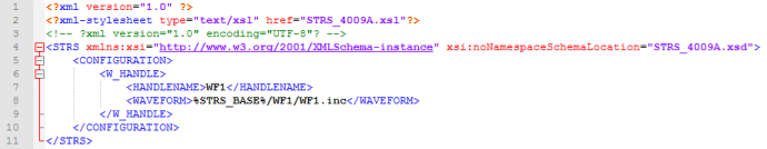
Here is the explanation, line by line:
- XML declaration.
- Extensible Stylesheet Language (XSL) file declaration.
- Comment.
- Open tag STRS and corresponding XML schema declaration.
- Open tag CONFIGURATION.
- Open tag W_HANDLE.
- Tag HANDLENAME containing WF1 as the handle name.
- Tag WAVEFORM containing the OE-specific name used to instantiate WF1 as a path to additional items to process.
- Close tag W_HANDLE.
- Close tag CONFIGURATION.
- Close tag STRS.
The OE-specific name is a file name containing the additional items to process, which are specified with their own XML configuration file and transformation process. This example of an application configuration file, for a sample application WF1, is shown in this NASA Technical Handbook in figure 7, Example of Predeployed Configuration File for Application WF1 for Appendix A.
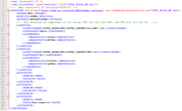
Here is the explanation, line by line:
- XML declaration.
- Extensible Stylesheet Language (XSL) file declaration.
- Comment.
- Open tag WAVEFORM and corresponding XML schema declaration.
- Tag WFNAME containing WF1as the class name.
- Tag WFACCESS with WF1 having no READ/WRITE access; that is, neither APP_Read nor APP_Write are implemented.
- Tag WFSTATE with final state as INSTANTIATED.
- Comment.
- Open tag LOADFILE.
- Tag LOADFILENAME containing the path to load WF1.out.
- Tag LOADTARGET containing SELF to indicate that it is loaded on the current GPP.
- Open tag LOADMEMORY.
- Tag MEMORYSIZE indicating that the size is 134k bytes.
- Tag MEMORYUNITS indicating that the size is measured in bytes.
- Close tag LOADMEMORY.
- Close tag LOADFILE.
- Open tag LOADFILE.
- Tag LOADFILENAME containing the path to WF1.bit.
- Tag LOADTARGET containing FPGA to indicate that it is loaded on the FPGA.
- Open tag LOADMEMORY.
- Tag MEMORYSIZE indicating that the size is 2670K gates.
- Tag MEMORYUNITS indicating that the size is measured in gates.
- Close tag LOADMEMORY.
- Close tag LOADFILE.
- Open tag ATTRIBUTE.
- Tag NAME containing A.
- Tag VALUE containing 5 as the value for A.
- Close tag ATTRIBUTE.
- Open tag ATTRIBUTE.
- Tag NAME with B.
- Tag VALUE containing 27 as the value for B.
- Close tag ATTRIBUTE.
- Open tag ATTRIBUTE.
- Tag NAME with C.
- Tag VALUE containing “Non-numeric” as the value for C.
- Close tag ATTRIBUTE.
- Close tag WAVEFORM.
The example in Appendix A splits the formatting into three parts to group the information logically. The following explanations further clarify the necessity and intent of Appendix A:
- There is no necessity or requirement for splitting the platform configuration files into hardware and software parts as shown in Appendix A.1 and A.2. Splitting up the description this way was just a logical way to organize the description.
- The format of the platform configuration file should allow some applications, devices, and services to be instantiated at boot-up or restart. Therefore, to use STRS_InstantiateApp to instantiate applications in all cases, the platform configuration file would specify the arguments. For this example, the OE-specific name argument referenced is the application configuration file name whose predeployed format is shown in Appendix A.3. The application configuration file may be independent of the platform configuration file.
6.10 C Language Naming Duplication
There will most likely be more than one application in an STRS radio. In the C language, there is no namespace support as in C++ or other object-oriented (OO) languages that scope the member functions to the class. Thus, there will be multiple implementations of the same STRS Application-provided API method names, starting with “APP_”, one in each implementation of an application.
One technique to allow multiple “instances” of C language applications could use APP_Instance to return a pointer to a table of pointers to the methods. Then, the OE could use these method locations to call the methods. This technique and variations are described in NASA/TM-2011-216948, Symbol Tables and Branch Tables: Linking Applications Together. The techniques specify the creation of a branch table or indirect address table for each application. To suppress the common method names, compile and link each application separately. When the table is registered with the OE, the OE could use the table to call the appropriate method.
Another technique to allow multiple “instances” of C language applications with the same method names depends on loading new applications one at a time, sequentially, and capturing the new method locations instead of the old at the appropriate point in the process. The method locations are saved in a structure associated with the STRS application and the appropriate method is called as needed. The flow chart shown in figure 8, Obtain Array of Pointers to Methods, gives some highlights. Note that, besides the method illustrated in figure 8, there are other ways of creating an array of pointers to the C language methods. This array of pointers may be used to invoke those methods later.
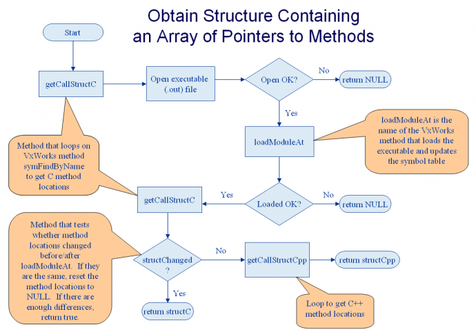
The technique demonstrated in figure 8 might not be possible on a platform that needs everything to be compiled and linked together ahead of time. Another technique would be to use message queuing to communicate between independent applications, but this technique might be awkward to use in practice. Another technique is to prepend the method name with a C-language class name equivalent.
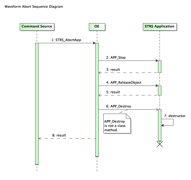
6.11 Sequence Diagrams Depicting STRS API Calls
The following sequence diagrams depict the relationship between the STRS infrastructure-provided Application Control API beginning with “STRS_” and the corresponding STRS Application-provided Application Control API beginning with “APP_.” The methods described for figure 1 are those that cause a change in state. In this NASA Technical Handbook, the methods depicted in figure 9, Simplified Sequence Diagram for STRS_InstantiateApp, figure 10, Simplified Sequence Diagram for STRS_AbortApp, and figure 11, Simplified Sequence Diagram for STRS_Configure, contain both those that cause a change in state as well as those that do not. In this NASA Technical Handbook, since an STRS Device inherits all the methods from an STRS application, as shown in figure 5, the methods in figures 9, 10, and 11 for STRS applications could apply to STRS Devices as well. In figures 9, 10, and 11, “Command Source” is used for the object, internal to the radio, either an STRS application or part of the OE, which calls the STRS infrastructure methods.
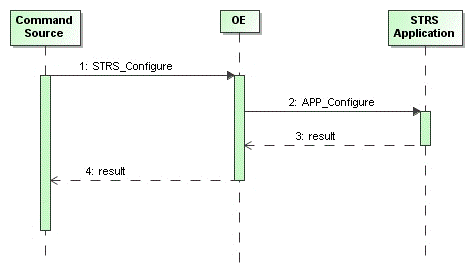
A sequence diagram for each row in table 1, Substitutions for Figure 11, can be made from the diagram in figure 11, by substituting the “COMMAND SOURCE TO OE” method in place of STRS_Configure and the corresponding “OE TO STRS APPLICATION” method in place of APP_Configure.
| COMMAND SOURCE TO OE | OE TO STRS APPLICATION |
|---|---|
| STRS_GroundTest | APP_GroundTest |
| STRS_Initialize | APP _Initialize |
| STRS_Query | APP _Query |
| STRS_Read | APP _Read |
| STRS_ReleaseObject | APP _ReleaseObject |
| STRS_RunTest | APP _RunTest |
| STRS_Start | APP _Start |
| STRS_Stop | APP _Stop |
| STRS_Write | APP _Write |
6.12 Why are APP_Instance and APP_Initialize Separate?
The APP_Instance and APP_Initialize methods are often used together successively but should not be combined because they have different functionality. The separation of APP_Instance and APP_Initialize supports encapsulation. It allows configuration to occur before APP_Initialize. In figure 9, STRS_InstantiateApp calls APP_Instance and then it may call APP_Configure and APP_Initialize, as specified by the configuration file. STRS_InitializeApp may do everything in one call or additional calls may be needed thereby giving the greatest flexibility. Also, note that APP_Instance is a convenience function containing a constructor and saving any application identifying information.
The Wireless Innovation Forum (formerly SDR Forum) and SWRADIO by the OMG put so much effort into SCA that it was decided to investigate these architectures. The result of that investigation was that the CORBA requirements and XML parser requirements took up a lot of memory and machine cycles but were not really necessary for NASA. One study showed that eliminating CORBA and an XML parser reduced the memory footprint by an order of magnitude. So, to save on SWaP for NASA’s space platforms, it was decided to create a similar STRS architecture without those disadvantages. After looking at use cases for NASA radios, very similar functionality to the SCA and SWRADIO was decided to be necessary. Similar method names to the application method names in SCA and SWRADIO were chosen for STRS. The reasoning was that it would be easy to take advantage of the many man-years of effort that had gone into defining those architectures, the Wireless Innovation Forum could comment on the STRS architecture due to the similarities, and that SDR design tools might be easier to use/generate for STRS applications.
A key recommendation from the Forum’s space working group was to align with the OMG SWRADIO specification where possible. To that end, mappings from the OMG SWRADIO PIM to the STRS platform-specific model (PSM) were discussed. There were only minor differences in the Space PIM that could map into STRS from OMG’s SWRADIO PIM that mapped into SCA. A quote from the Forum’s study:
The SDR Forum recommended that the STRS align with the SDR Forum, the OMG, and the IEEE SCC41 for purposes of distributing the burden and cost of non-recurring engineering (NRE) across NASA and all consortia members contributing to the STRS, and to further broaden and enhance the quality of the implementation and deployment of STRS-based standards.
NASA’s configuration files could be much simpler, because NASA’s radios were less distributed with no dynamic aspects needed to be specified in the configuration files. Furthermore, it was decided that by preprocessing any XML configuration files, a much simpler parser could be used on much simpler data.
In considerations for NASA-STD-4009A, it was determined that NASA’s radios could be even simpler and that some further complexities could be eliminated. Such changes eliminated the possibility of harmonization with SCA but were more flexible regarding use with Core Flight Software (cFS) and other frameworks.
Security aspects need to be considered for any STRS radio. There are currently no STRS requirements for security, and it is assumed to be up to the project/mission to define any security requirements. It was determined that NASA radios typically do not require DO-178, Software Considerations in Airborne Systems and Equipment Certification; and red/black separation. Security is needed to:
- Verify/validate external commands such that:
- They come from the appropriate source (e.g., using data in a CCSDS wrapper).
- They have not been compromised (e.g., using encryption, signing, parity bit, checksum, cyclic redundancy check).
- They are in the appropriate format for commands.
This is usually defined by the command and control for the mission and not by STRS. The security functions should be encapsulated, separate from the external command and control interpreter, so that the functionality may be changed if necessary without affecting the STRS application implementation. This functionality may be invoked by the STRS OE implementation or as a service for over-the-air command and control.
- Verify/validate internal commands; i.e., do not allow the radio to try to do anything risky or make itself inoperable.
- Do not allow radio to call methods for which the handle ID is inappropriate.
- Restricting the radio as to what it can do is left as a possible project/mission requirement. For example, one might restrict one waveform from aborting any other waveform. In this case, it is suggested that a table be configured containing allowed or disallowed commands and the associated source(s) handle names and target(s) handle names for which the command applies such that the table could be used to validate a command.
- Specifying a key to allow the radio to override the restrictions of item “b(2)” is also left as a possible project/mission requirement. In which case, security keys and an authentication method is required.
Security requirements are defined by the project/mission and not by STRS. The security functions of item “b(2)” and item “b(3)” should be encapsulated so that the functionality may be changed if necessary, without affecting the STRS application implementation. This functionality may then be invoked by the STRS infrastructure implementation.
6.15 What is Configurable Hardware Design?
The term “configurable hardware design” is used throughout the STRS documentation to signify the items required to capture the digital logic of the hardware that can be configured remotely, such as an FPGA. Configurable hardware design includes the items created to document the design of the hardware, including the source code (e.g., very high speed integrated circuits (VHSIC) hardware description language (VHDL), Verilog ) and the loadable files (e.g., FPGA image).
The term “configurable hardware design” replaces the commonly used term “firmware” in earlier versions of STRS documentation. Many definitions for firmware, including the latest IEEE definition which was written in 1990, state that firmware resides in read-only memory and cannot be modified. The changing definition of “firmware” would likely lead to confusion, and a new term was selected for the STRS documentation. Additional terms such as “complex electronics,” “configurable logic device,” “programmable logic device,” and “software” were considered, but each term was rejected due to potential confusion or implied limitations if the term was used.
The SDR community is unique in that it uses GPPs and configurable hardware design in a single application. The term “software” in some contexts of the STRS (and other SDR-related) documentation may include configurable hardware design. For example, whenever the term software defined radio is used, both GPP and configurable hardware design are included. The STRS architecture does not dictate processes or organizational structure for use in developing the software or configurable hardware design. The project developing the SDR or application has to dictate the required process.
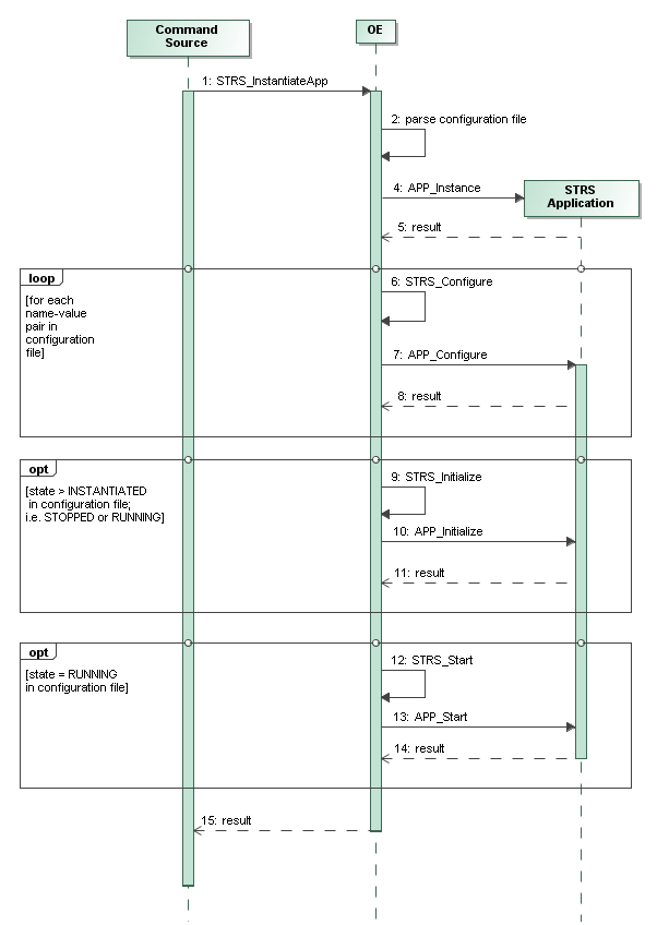
6.16 Why is there STRS_InstantiateAPP and no STRS_Instance method?
The application instantiation process should not only instantiate the application but ensure that the application starts in a known state. The application may be comprised of multiple items that are loaded as part of the application instantiation process. The application instantiation process should also ensure that data is configured consistently. This potentially multi-step process was most easily customized by putting the variable instantiation data in a configuration or script file. The configuration file is parsed and processed by the OE in STRS_InstantiateApp before calling any methods in the application. Figure 10 illustrates that STRS_InstantiateApp could call multiple application-provided methods as needed to begin execution in a consistent well-defined manner. APP_Instance is the only method that is required to be called, but APP_Configure is highly encouraged so that data does not have to be hard-coded in the application but may be changed according to predetermined conditions and known upon application start-up in a consistent manner. This is not a simple one-to-one relationship between STRS_InstantiateApp and the other methods it invokes; whereas, it is a simple one-to-one relationship for most of the other STRS application-provided application control methods and the corresponding STRS infrastructure-provided application control methods.
To ensure that a user could not instantiate an application in an unknown state, STRS_Instance that invoked APP_Instance was not allowed. STRS_Instance calling APP_Instance was disallowed to discourage a user from instantiating an application in an unknown state. The method name STRS_Instance was not reused for the multi-step process in order to highlight the difference between simple instantiation of an application and instantiation of an application using a configuration file.
6.17 Uniqueness of Handle Names and IDs
A handle name is a C language character string that specifies the name of a specific instance of an STRS resource that may be an application, service, device, file, or queue. It is used in external commands and messages. It is usually the same at each start-up of the radio platform unless specifically changed. A handle ID is a numerical value determined by the infrastructure that could contain an index, hash, address, or other data that help the OE locate the information necessary to access the resource. It is used in internal method invocations and is restricted so that STRS_ValidateHandleID can determine whether there is an error and STRS_GetErrorQueue can indicate which error queue to use. It is often different at each start-up of the radio platform even if the handle name remains the same.
6.18 Are there any exception-safety rules?
The methods in the STRS APIs are not allowed to throw exceptions. Suppose a pre-existing library contains functions that can throw exceptions and suppose a method in the STRS APIs calls the library function. Then the method in the STRS APIs must catch all exceptions that the library function can throw. The return result from the method in the STRS APIs will indicate whether there has been an error or not.
6.19 What does it mean that an STRS Device or STRS Service may be part of the OE?
An STRS Device or STRS Service is an optional part of the OE depending on the project/mission requirements. The intention was that STRS Devices and STRS Services encapsulate non-portable functionality or functionality that applies over multiple waveform applications. Also, a further intention was that the STRS Devices have additional capabilities beyond that allowed to an STRS application as if the STRS Device were part of the OE. It should be required by the project that the platform provider create a sample application that uses a sample STRS Device to exercise both the hardware and software for testing and that serves as a model for what can be done by the application developer. The STRS Device would be included with the corresponding sample STRS application. An STRS Device would be specified as part of the OE, for example, if the device is not really programmable but can be adjusted or turned on/off by the HAL.
To access the specialized hardware containing application functionality, the STRS Device must correspond to an STRS application such that the application developer must be able to modify the sample and compile it with the user’s STRS application. The application developer needs to wrap the HAL invocation(s) into STRS Devices and handle the message format to/from the application and specialized hardware.
6.20 How does the application know how to put the data (address, command, data) into the buffer in the specialized hardware?
Use the STRS_Configure method to change settings that are configuration related and do not change at every message. The contents and format of the buffer can be defined for your application.
An STRS Device is a bridge between the waveform application and the HAL. So, an application could be a sink for some data created elsewhere by implementing APP_Write. That application could call STRS_Write to send the data from the application to the STRS Device that also acts as a sink by implementing APP_Write in the STRS Device. Then the STRS Device could use the HAL to send the data to the specialized hardware.
It has been suggested that EDS be used to configure STRS Devices. The CCSDS has a Draft Recommended Standard for Spacecraft Onboard Interface Services – XML specification for Electronic Data Sheets for Onboard Devices, CCSDS 876.0. Allowing the use of CCSDS EDS has merit and does not conflict with the STRS requirements since the data sheet configuration file would be in XML as required and may be transformed to a deployed format if needed. Since the CCSDS EDS allows extensions, any specific requirements in this area are better left to the Project.
6.21 Can STRS applications run in multiple address spaces?
Yes; however, multiple address spaces for multiple STRS applications would require some means of enabling the OE to call the STRS application-provided methods and vice versa. Things can get as complicated as necessary depending on the desired distribution of the software across the address spaces and the availability of the appropriate middleware or equivalent. Using STRS_API as a representative infrastructure-provided interface called from some command source and APP_API as a corresponding application-provided interface implemented within some application, some examples could be depicted as:
- STRS_API1 -> APP_API1
- STRS_API1 -> APP_API1 -> STRS_API_Ethernet -> STRS_API2 -> APP_API2
- STRS_API1 -> APP_APItx ~~~ APP_APIrx -> STRS_API2 -> APP_API2
- STRS_API1 -> distribution point -> … -> collection point -> APP_API2
- STRS_API1 -> distribution point -> … -> collection point -> APP_API1 -> STRS_API2 -> distribution point -> … -> collection point -> APP_API2
These are not exhaustive.
For 1 above, where the call is direct, dynamic linking may be used; but both must be in the same address space. The “this” pointer or equivalent is used as needed for the STRS API methods to call the corresponding APP API methods. For 2 or 3 above, the call is direct to some application object that controls the access to another application in another address space (or even another radio) via Ethernet, remote procedure call (RPC), over-the-air (OTA) signal, Bluetooth, etc. For situations where this will not work, including multiple address spaces as depicted in 4 above, any middleware may be inserted in between, such as CORBA. In 5 above, an additional level of complication was added, just to show one of the many combinations. Some of these ideas were used when a graphical user interface (GUI) was added that was situated on a different computer using a different operating system.
The following figure 12, Multiple Connected Radios, can be used to illustrate 2 or 3 above when the networking is encapsulated in applications for sending and receiving using Ethernet or other means of message passing across the address spaces. For the figure below, WF1 is the command source for STRS_API1 and WFtx is the sink for the corresponding command. After passing through the connection, the same command is repeated where now the dependent command source for STRS_API2 is WFrx and WF2 is the sink. One cannot get greater separation than when the applications reside in what appear to be different radios. The following figure can be used to illustrate 4 above when the connection from WFtx to WFrx is replaced by middleware marshalling and unmarshalling the data.
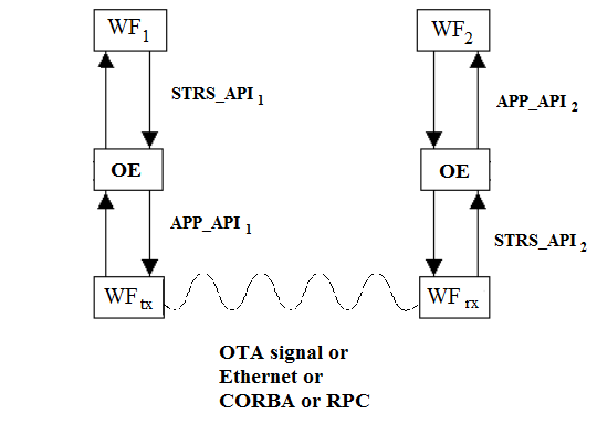
6.22 Does an STRS application require a main entry point?
No; the STRS Architecture Standard does not require that a main program be defined for an STRS application. An STRS application may require a main entry point if specified by the platform provider.
The idea was to leave as much leeway as possible while having much of the initialization and control code being portable. The word “application” was used in its broadest sense so that it can include a main program or not, depending on the STRS infrastructure-required interfaces. The infrastructure-provider is obligated to describe the interface mechanism so that additional applications may be written or ported. The infrastructure must contain a main entry point or the equivalent so it can be started.
The integrator must have all applications, shared libraries as well as main at compile and link time for proper linking on the target. The dynamic linking/loading capabilities of some operating systems may be useful to add additional applications at a later time as needed.
6.23 How is STRS_TimeSynch used to adjust time?
Pseudocode for STRS_TimeSynch might be:
    STRS_TimeSynch(me,refDev,kind',tgtDev,kind,stepMax) {
        STRS_GetTime(me,refDev,refbase, kind', refkind); // Get reference time
        STRS_GetTime(me,tgtDev,tgtbase, kind,  tgtkind); // Get target time
        tgtold = tgtkind;                     // Old time
        delold = tgtold - tgtbase;            // Old delta
        tgtkind = refkind';                   // Synchronization/new time
        deltgt = tgtkind - tgtbase;           // Compute/new delta
        chg = tgtkind - tgtold;               // compute change.
        If (stepMax == 0)                     // Test if jump.
        {                                     // No stepMax => jump.
            rtn = 0;                          // OK as jump. Return zero.
        } else if (chg < -stepMax)            // Test change against step size.
        {                                     // Change is negative and bigger than step size.
            rtn = (-chg - stepMax) / stepMax; // Return amount left to do.
            deltgt = delold - stepMax;        // Increase negatively by a step size.
        } else if (chg <= stepMax)            // Test change against step size.
        {                                     // Change is smaller than step size.
            rtn = 0;                          // OK, as jump. Return zero.
        } else {                              // Change is positive and larger than step size.
            rtn = (chg - stepMax) / stepMax;  // Return amount left to do.
            deltgt = delold + stepMax;        // Increase by a step size.
        }
        STRS_SetTime(me,tgtDev, kind, deltgt);
        return rtn;
    }
(See 6.24.)
6.24 How is Clock Rate Adjustment Used?
A clock may drift due to age or environmental factors or relativistic changes. STRS provides for a clock rate adjustment using STRS_SetTimeAdjust. A user would need to set up loops to check the clock periodically for drift. One way is to use STRS_TimeSynch with a maximum time step that returns the number of maximum time steps left to do. If this seldom returns zero, a time adjustment is in order. The size of the adjustment is clock-dependent. Iterate until the clocks generally stay in synch.
(See 6.23.)
6.25 What is OE-Specified String for the Application to be Instantiated?
The STRS_InstantiateApp method contains an argument described as: The string used to identify the application for instantiation that may impose additional operations to be performed as documented by the platform provider. The project manager and platform provider will decide whether this parameter is to be a class name, or a file name. Usually, the latter is selected to be a software configuration file or script file to give the greatest flexibility for the STRS infrastructure to specify default or initial attributes of software items pertaining to the platform or applications, services, and devices contained on an STRS radio. Application-specific information for configuration and customization of installed applications may be provided, as well as information for the STRS infrastructure to use to instantiate applications on the radio GPP. Such files provide STRS application developers with flexibility in choosing parameters and values deemed pertinent to the implementation. In a specific case actually encountered, the parameters within the application changed based on ambient conditions such that a set of calibration tests were performed and the results stored in a configuration file. Using a configuration file allowed the code to remain unchanged.
For a configuration file, the use of XML version 1.0 is recommended to define the STRS platform and application configuration data because XML has the ability to identify configuration information in a standard, human-legible, precise, flexible, and adaptable method. XML is a markup language for documents containing structured information that contains both content and some indication of what role that content plays. XML defines tags containing or delimiting content and showing the relationships between them (see http://www.w3.org/XML/). Because of the extra overhead required to transmit and process XML-formatted data, it is anticipated that the XML configuration file would be preparsed, additional error checking on the file will be performed, and the XML file transformed into a simpler, more compact form prior to transmission. This process will reformat the configuration file into an appropriately optimized configuration file, which will subsequently be loaded into the radio.
An XML Schema Definition (XSD) file contains an XML schema describing the structure and constraining the content of XML documents (See http://www.w3.org/XML/Schema). An XML schema can provide error checking of allowable values, dependencies, and range limits of configuration parameters.
An XML interface tool could be used to create and modify platform and application configuration files. When used with an XML schema, these tools standardize the XML data entry, enforcing error checking and interdependency checks to ensure that the entered data are correct and within the hardware and software limits.
The XML should be preprocessed to a platform-specific format to optimize space on the STRS radio while keeping the equivalent content. Figure 13, XML Transformation and Validation, illustrates the relationships between an XML file and its corresponding schema, as well as representing the preprocessing of the XML file in a simplified form using Extensible Stylesheet Language (XSL). XSL is a family of recommendations for defining XML document transformation into text for presentation. (See http://www.w3.org/Style/XSL/.)
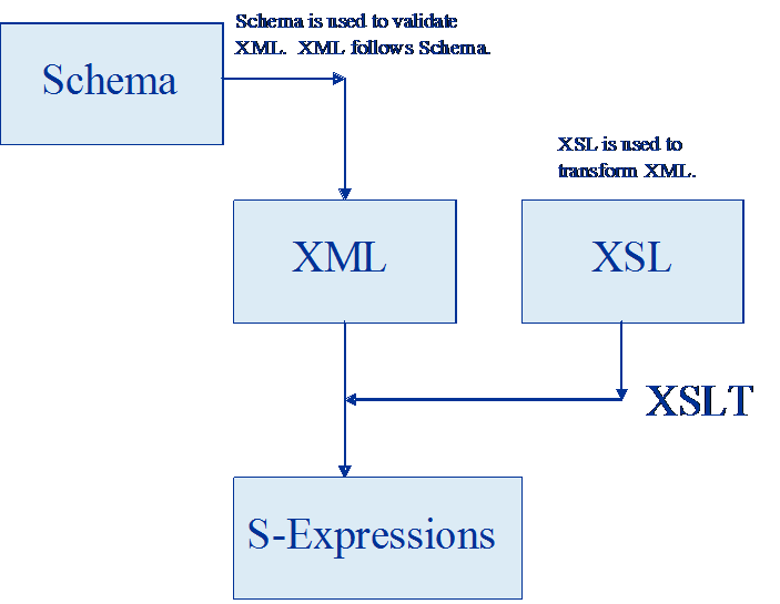
The application configuration files would be developed by the STRS application developer and STRS integrators using information obtained from both the STRS platform provider and the STRS application developers. The STRS integrators use the application configuration files to install the applications on the platform. These roles may overlap at times.
The STRS platform provider documents the method to describe and use the hardware and software environment for the STRS infrastructure. Developing platform configuration file(s) is the likely method to be used by an STRS platform provider to identify the existence of the different hardware modules and their associated configuration files to allow the OE to instantiate drivers and test applications. An STRS platform configuration file may be used when starting the STRS infrastructure to configure various properties of the STRS platform. Configuring these properties at run-time allows greater flexibility than configuring them at compile-time. To increase the runtime flexibility of the STRS platform, the STRS infrastructure is likely to use deployed platform configuration files to determine the existence and attributes of the files, devices, queues, waveforms, and services contained on the STRS radio. Attributes of files, devices, and queues could include access (read/write, both, or append), type (text or binary), and other properties. The name of the starting configuration file(s) may be provided to the STRS infrastructure upon initialization. The predeployed platform configuration files should contain platform configuration information such as the following:
- Hardware module names and types.
- Memory types, sizes, and access.
- Memory mapping.
- Unique names and attributes of files, devices, queues, services, and applications known to the OE at boot-up.
A predeployed STRS application configuration file could be created by the STRS integrator using platform information, the XML schema supplied by the STRS platform provider, and application information provided by the STRS application developer. The deployed application configuration file would be used by the infrastructure (see the STRS_InstantiateApp method) when starting the STRS application to configure various properties of the STRS application. Configuring these properties at run time allows greater flexibility than configuring them at compile time. For example, one might configure the STRS handle names of files, devices, queues, waveforms, and services needed by the STRS application so that these can be easily changed. Since a service is actually an application that has been incorporated into the STRS infrastructure, the format of the application configuration file should be a subset of the format of the platform configuration file as specified by the schema. If any STRS application resources need to be loaded separately into memory or into a device, such as an FPGA, before the STRS application can function properly, these should be specified in the configuration file for that STRS application.
The predeployed STRS application configuration file may identify the following application attributes and default values:
- Identification.
- Class name.
- State after processing the configuration file (if applicable) or script to execute to get there. This is as documented by the platform provider.
- Any resources to be loaded separately (if applicable).
- Filename of loadable image.
- Target on which to put loadable image file.
- Target memory in bytes, number of gates, or logic elements.
- Initial or default values for all distinct operationally configurable parameters.
The most common transformation of STRS configuration files uses name/value pairs divided by a separator for the deployed format.
6.26 STRS Radio Startup Process, Platform Diagnostics, and Built-in Test?
The platform boot process generally has many parts, depending on the project requirements for safety and confidence. Built-in testing is often performed even before the STRS OE is initialized. Once the STRS OE is started, it is expected that further platform diagnostics be reported to the STRS OE using the STRS APIs as required by STRS-2. The STRS radio is expected to have a known power up condition where it is ready to receive commands, send telemetry, and transmit and receive communications according to the project requirements. Upgrades to the boot process could allow changes to the OS, OE, and/or applications to be made in a secure fashion.
6.27 Cognitive, Navigation, and Other Services
The STRS architecture allows STRS radios to provide cognitive, radiometric tracking, navigation, and other services that are integrated with communication services. Cognitive services obtain metrics to monitor the radios’ operation, learns how to optimize the performance of the radio, and modifies the operation of the radio accordingly. Radiometric tracking is the process of measuring the characteristics of radio signals that have been transmitted (potentially over several legs) in order to extract information relating to the signal’s change in frequency and/or time of transit. A radio has the fundamental component needed for tracking – a radio signal. The SDR simplifies the navigation architecture because it minimizes mass, power, and volume requirements while maximizing flexibility. An SDR provides the flexibility to respond to different mission phase requirements and to dynamic application requirements where signal structures may change. This is the fundamental reason for considering the implementation of an SDR with tracking and navigation functionality.
Various editors and compilers usually use the file extension (after the last period) to make a decision about the type of file and how to use it so that it is helpful to have different code and header file extensions for C and C++. Furthermore, when C code is used in a C++ method, ‘extern “C”‘ may be used to indicate that that the interface is to be that for C rather than C++. For example, to declare a C language method in C++:
    extern "C" {
    // Function to report statistics (C language)
    void MyServiceReportStatistics( MyServiceType myType );
    } // End of extern C
There is a way of using a #ifdef to check whether the code is in C code or C++ code, if necessary, when the same header file is used for both C and C++. For example:
    #ifdef __cplusplus
    extern "C" {
    #endif
      . . .
    #ifdef __cplusplus
    }
    #endif
APPENDIX A
EXAMPLE CONFIGURATION FILES
A.1 STRS Platform Configuration File Hardware Example
Appendix A introduces examples of platform and application configuration files, necessary for application execution and platform initialization. Appendix A also describes example configuration file formats. STRS configuration files contain platform- and application-specific information for the customization of installed applications. These examples are not required formats. They are intended to illustrate some considerations that STRS platform providers and STRS application developers should take into account when designing their configuration file formats.
An example of the format of the portion of an STRS platform configuration file that deals with hardware is implemented in an XML schema. This format is shown in figure 14, Example of Hardware Portion of STRS Platform Configuration File.
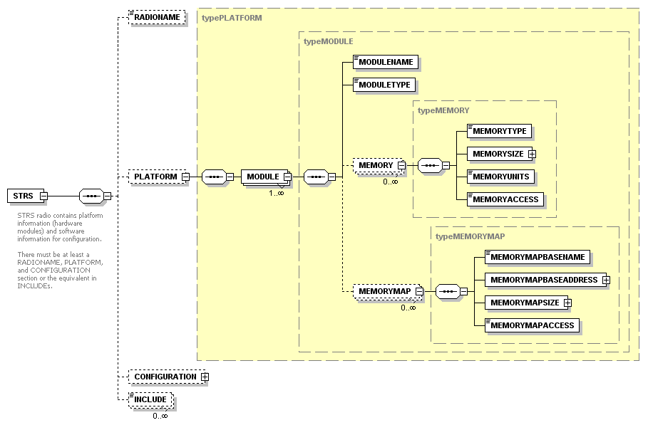
Figure 14 – Example of Hardware Portion of STRS Platform Configuration File (D)
For any GPP, the memory size and memory location should be specified in bytes. Rationale for International Standard-Programming Languages-C states the following:
- “All objects in C must be representable as a contiguous sequence of bytes, each of which is at least 8 bits wide.”
- “Any object can be treated as an array of characters, the size of which is given by the sizeof operator with that object’s type as its operand.”
- “It is fundamental to the correct usage of functions, such as malloc and fread that sizeof(char) be exactly one.”
Therefore, for consistency across C and C++ implementations, bytes are used.
MODULE list – A list of hardware modules having memory able to contain data and executable software.
- MODULENAME – The unique name for each hardware module accessible from the current GPP. The current GPP is denoted by SELF.
- MODULETYPE – The name of the hardware type. The hardware module types may be GPP, RF, FPGA, DSP, ASIC, and so forth.
- MEMORY list – A list of memory areas of various types. See below for further information.
- MEMORYTYPE – Memory type may be RAM, EEPROM, etc.
- MEMORYSIZE – The number of memory units.
- MEMORYUNITS – Memory units may be BYTES or GATES. For any GPP, the size is to be in BYTES.
- MEMORYACCESS – Memory access for the memory. Access may be READ, WRITE, or BOTH.
- MEMORYMAP list – This list provides the base addresses and memory size of regions of the current GPP RAM (SELF) that are memory mapped to the module: that is, memory mapped to an external device. There may be more than one item in the list when different parts of memory are either not contiguous or are used for different purposes. See section A.2, under DEVICE list, in ATTRIBUTE list, for memory offsets specific to the device associated with a name.
- MEMORYBASENAME – A unique identifier for the portion of memory mapped to the module.
- MEMORYBASEADDRESS – The starting byte address reserved for memory mapping.
- MEMORYSIZE – Number of bytes starting at the base address reserved for memory mapping.
- MEMORYACCESS – Memory access for the portion of memory mapped to the module. Access may be READ, WRITE, or BOTH. The access defined here may be different from the memory access defined in the previous section when part of the memory is used for one purpose and another part is used for a different purpose.
A.2 STRS Platform Configuration File Software Example
An example of the format of the portion of an STRS platform configuration file that deals with software is implemented in an XML schema. This format is shown in figure 15, Example of Software Portion of STRS Platform Configuration File.
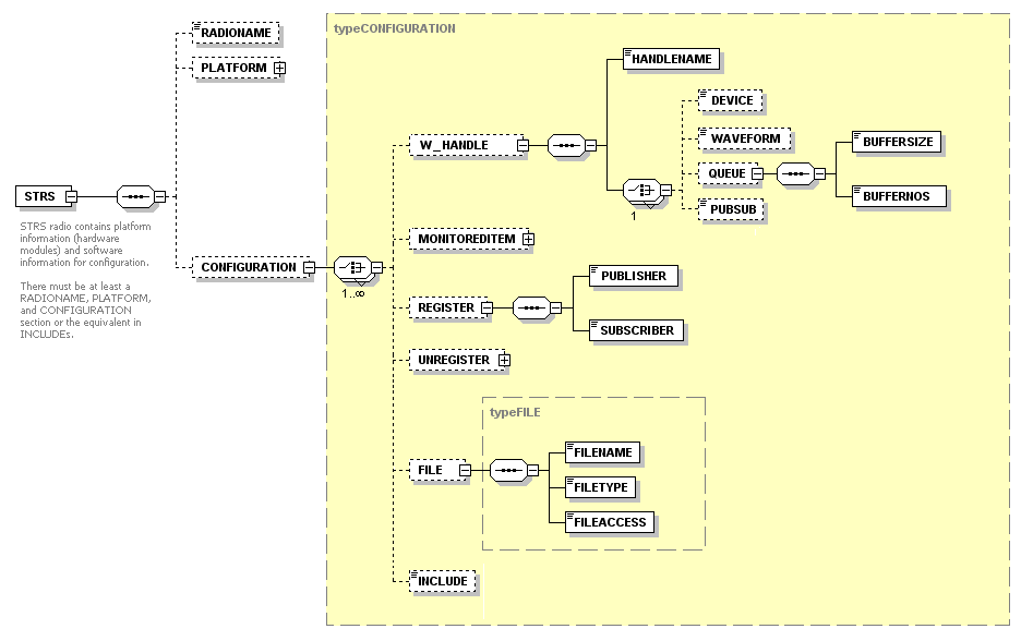
FILE list – A list of files to read, write, both, or append from multiple locations using a handle ID.
- FILENAME – Storage area name or fully qualified file name.
- FILETYPE – The file type may be TEXT or BINARY.
- FILEACCESS – The file access may be READ, WRITE, BOTH, or APPEND. BOTH implies update, that is, READ and WRITE.
W_HANDLE list – This is a list of unique STRS handle names and corresponding objects.
- HANDLENAME – A unique shortened form of the Device, Waveform, Queue, Pub/Sub name to use as a character identifier to be used in messages and for obtaining the handle ID.
- DEVICE – OE-specific name to instantiate the device. A device is software that acts as a proxy for some hardware connection.
- WAVEFORM – OE-specific name to instantiate the application.
- QUEUE list – The information necessary to create a FIFO queue.
- BUFFERSIZE – The maximum size of messages in queue.
- BUFFERNOS – The maximum number of messages in queue.
- PUBSUB list – OE-specific name for the Pub/Sub.
REGISTER list – The correspondences between queues and subscribers. This couples publishers and subscribers. UNREGISTER is the same as REGISTER except it decouples publishers from subscribers.
- PUBLISHER – The name of the queue that the publisher uses to send data to the subscribers. Used in messages and for obtaining the handle ID.
- SUBSCRIBER – A handle name for a subscriber. Used in messages and for obtaining the handle ID.
MONITOREDITEM list – A list of monitored items that are tested to indicate the health of the system.
- ATTRIBUTENAME – The name of the property whose value is to be tested in a monitored component.
- HANDLENAME – The handle name defines the monitored component from which to obtain the value corresponding to the attributeName.
- DELAY – A positive value represents the nominal time delay between successive automated tests of the monitored component. A nonpositive value indicates that the test is to be requested.
- TESTTYPE – The type of test to apply to the property to ascertain whether the value indicates the monitored component is healthy. Examples include testing for exact values, within ranges, or by use of operations in Reverse Polish Notation (RPN).
- EXACT – Monitored value is to be one of the values in the value list.
- EXCLUDE – Monitored value is not to be in the value list.
- BETWEENII – Monitored value is to be between the pairs of values in the value list including both end points.
- BETWEENIX – Monitored value is to be between the pairs of values in the value list including the low end point and excluding the high end point.
- BETWEENXI – Monitored value is to be between the pairs of values in the value list excluding the low end point and including the high end point.
- BETWEENXX – Monitored value is to be between the pairs of values in the value list excluding both end points.
- RPN – The attributeName, values to be tested, and operators are to appear in the value list using RPN. RPN uses sequences of one or two arguments followed by an operator. The result of applying the operator replaces the original sequence used, and the process is repeated until there are no more operators. The attributeName for the monitored value is replaced, in the RPN formula, by the corresponding property value. For example, the sequence of data and operators in the VALUE list for testing the property named D in RPN: “0;D;LT;D;500;LE;AND” is equivalent to (0<D && D≤500).The current set of operators includes the following:
AND, OR, XOR, NOT, EQ, NE, GT, GE, LT, LE, PLUS, MINUS, MULTIPLY, DIVIDE, MOD, MIN, MAX.
If floating point is required or allowed, the set of operators could be augmented with the following: SIN, COS, TAN, ASIN, ACOS, ATAN1, ATAN2, SINH, COSH, TANH, ABS, EXP, LOG10, LN, SQRT, FLOOR, CEIL, ROUND, POW.
VALUE list – A list of values and possibly operations used corresponding to the value of TESTTYPE.
- For example, if TESTTYPE is EXACT, the VALUE list will contain {512,1024,2048,4096} if those are the allowed values.
- If TESTTYPE is EXCLUDE and odd numbers between 1 and 10 are not allowed, the VALUE list will contain {1,3,5,7,9}.
- If TESTTYPE is BETWEENII and the attribute D is allowed between 0 and 500, inclusive (0 ≤ D ≤ 500), the VALUE list will contain {0,500}. Because the TESTTYPE is BETWEENII, the lower limit, 0, is included and the upper limit, 500, is included.
- If TESTTYPE is BETWEENIX and the attribute D is allowed between 0 and 500 (0 ≤ D < 500), the VALUE list will contain {0,500}. Because the TESTTYPE is BETWEENIX, the lower limit, 0, is included and the upper limit, 500, is excluded.
- If TESTTYPE is BETWEENXI and the attribute D is allowed between 0 and 500 (0 < D ≤ 500), the VALUE list will contain {0,500}. Because the TESTTYPE is BETWEENXI, the lower limit, 0, is excluded and the upper limit, 500, is included.
- If TESTTYPE is BETWEENXX and the attribute D is allowed between 0 and 500, exclusive (0 < D < 500), the VALUE list will contain {0,500}. Because the TESTTYPE is BETWEENXX, the lower limit, 0, is excluded and the upper limit, 500, is excluded.
- If TESTTYPE is RPN and the attribute D is allowed between 0 and 500 (0 < D ≤ 500), the VALUE list will contain {0,D,LT,D,500,LE,AND}.
A.3 STRS Application Configuration File Example
An example of the format of an independent STRS application configuration file in XML is shown in figure 16, Example of STRS Waveform Configuration File.
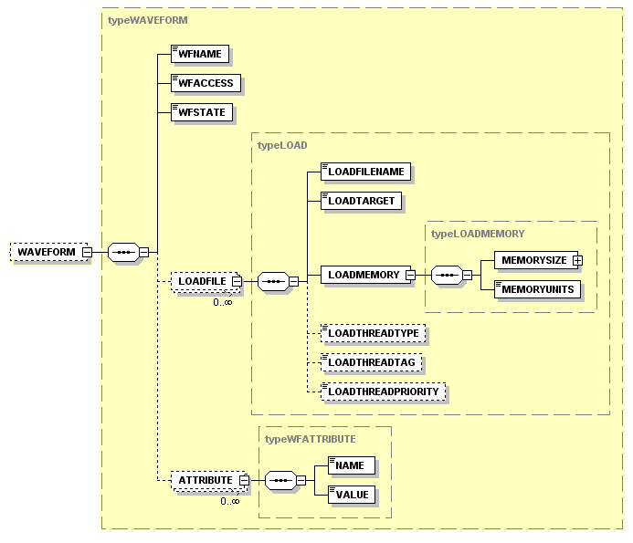
WAVEFORM list
- WFNAME – If coded in C++, this is the application class name. If coded in C, this is an equivalent class name.
- WFACCESS – The access to the application may be specified as READ, WRITE, BOTH, or NONE. READ indicates that the application implements APP_Read(). WRITE indicates that the application implements APP_Write().
- WFSTATE – The state at which the application is left after processing the configuration file. The state may be INSTANTIATED, STOPPED, or RUNNING.
- LOADFILE list – A list of files to be loaded for execution if not already loaded. Usually, the software for the application on the current GPP (SELF) should be loaded before the configurable hardware design so that the software can load and configure the software or configurable hardware design as necessary.
- LOADFILENAME – Storage area name or fully qualified file name
- LOADTARGET – Module name for the device on which the file is instantiated. The load process is determined by the corresponding MODULE information (see A.1).
- LOADMEMORY
- MEMORYSIZE – The number of memory units.
- MEMORYUNITS – Memory units may be BYTES or GATES. For any GPP, the size is to be in BYTES.
- LOADTHREADTYPE
- LOADTHREADTAG
- LOADTHREADPRIORITY
- ATTRIBUTE list – A list of properties set as default during initialization.
- NAME – Name of the attribute
- VALUE – Value of the attribute
The format of an independent STRS device configuration file in XML would be similar. An example of the format of an independent STRS application configuration file in XML is shown in figure 17, Example of STRS Device Configuration File.
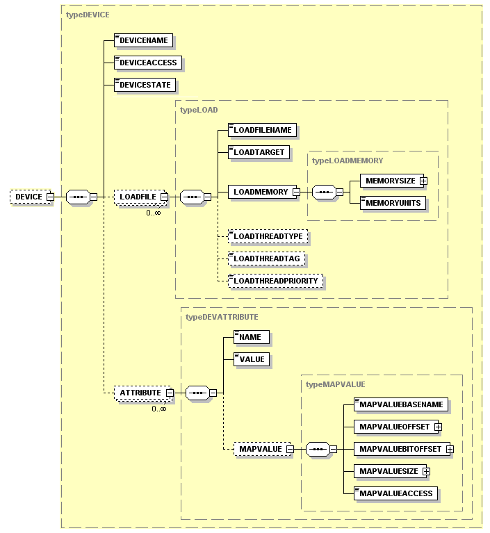
The difference being that the ATTRIBUTE tag could have additional parameters describing memory mapping.
- ATTRIBUTE list – A list of properties set as default during initialization.
- NAME – Name of the attribute.
- VALUE – Value of the attribute.
- MAPVALUE list – Location in memory of the attribute when memory mapped. A location is to be unique to the associated device.
- MAPVALUEBASENAME – A unique identifier for the portion of memory mapped to the module. This is to match a MEMORYBASENAME value defined in section A.1, under MODULE list in the MEMORYMAP list.
- MAPVALUEOFFSET – Offset from the address of baseName as defined in the module list’s memory map list.
- MAPVALUEBITOFFSET – Bit offset from the high order position to begin.
- MAPVALUESIZE – Number of bits in which to store the value.
- MAPVALUEACCESS – Memory access may be READ, WRITE, or BOTH.